Description
Chlor Alkali producers are going through major changes in regard to process technology and public acceptance. They are being attacked by the public as producers of an environmentally hazardous compound and polluters due to their use of mercury. Although Hg leakage has been reduced to a negligible level and current processes do not use mercury at all, the image in the eye of the public is difficult to change and hard work is required to improve reputation. Restriction in the transportation of chlorine is forcing many chemicals companies to produce their chlorine supply locally. Although a sensitive process with regard to brine quality, it has the lowest energy consumption and does not require Hg.
Brine is used in the production of chlorine and caustic soda, two basic chemicals used in many industries. In Chlor- Alkali plants, brine is introduced into clarifiers. Salts are removed and the over-flow is sent to polishing filters (Pulse jet candle filters). Ion exchangers are then used downstream of the polishing filters.
Maintaining and repairing ion exchange systems is quite costly. Producers of chlor-alkali rely on upstream filters to keep them safe. If particulates pass through the polishing filters, the ion exchangers become clogged fast and must be serviced or replaced at a high cost.
ABHIMART Pulse jet candle filter brine polishing systems are specifically designed for pre-filtration to protect expensive ion exchange systems in chlor-alkali production. As the membranes in the electrolyser are extremely sensitive to impurities, the quality requirement of the brine (typically less than 0.3-0.5 ppm suspended solids) is of major importance.
The ABHIMART Pulse jet candle filter has originally been designed with the filtrate quality aspect as a key factor. Then, all components in the production chain have been analyzed so that system reliability could be improved and brine loss reduced. It is therefore not surprising that major producers and engineering offices have included the equipment in their processes. All materials in contact with the brine are either high performance plastic components, rubber lined parts or titanium. The filter media have been designed to reach the high-quality requirements and to allow for both dry (around 70% dry content) and slurry discharge of the filtered solids. Alpha cellulose is used for both precoat and body feed and specific throughput is above 2000 lit/m2-h with a cycle time of roughly 48 hours. Where vacuum purified salt is used, brine purification is limited to a polishing step; where rock salt is used, further separation steps are added. As the overflow of a static decanter reaches 30-50 ppm and an anthracite filter 5-15 ppm, a polishing step is still indispensable.
What is Candle Filter?
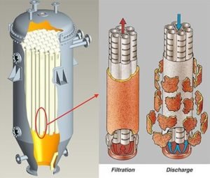
Candle filter is a compact filter, which is mainly used for clarification filtration of low content of liquid and solid. It can achieve high yield, the discharge of dried and wet filter cake, and the treatment of various filtrates, and it is very suitable for filtering NaCl brine, Activated carbon and Nickel catalyst. The candle filter design is designed for the need in the production process requiring a harsh working environment. The system can be automatically recycled and filtered without stopping the operation of the system, which can effectively avoid downtime and the operation safety of personnel. Candle type filters are pressure filters, running in batch cycles. They are seen in dispose of titanium dioxide, high-temperature flue gas, brine clarifications, fine chemicals, and many other applications requiring the highly efficient separation of filter cakes.
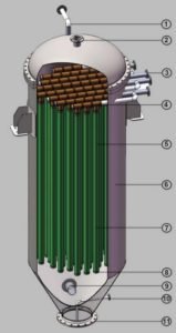
- Vent nozzle
- Safety Relief valve
- Filtrate nozzles
- Sub headers
- Filter element
- Pressure vessel shell
- Filter medium (cloth )
- Cloth clamp ring
- Brine feed nozzle
- Heel volume nozzle
- Solid-residue discharge nozzle
Candle Filter - Working Principle
Candle Filter is basically a Pressure Filter working on surface filtration principle and is suitable for both pre-coat and direct filtration. However depending on the liquid to be filtered and the nature of solids in the feed, pre-coating could be necessary.
The purpose of pre-coat is:
- To prevent the filter septum from becoming clogged by impurities and thus prolonging septum life.
- To give immediate clarity.
- To facilitate cleaning of the septum at the end of the filtration cycle.
Pre-coat Filtration involves the following Major steps.
- Pre-coat Mixing And Filling Of Filter
Filtered liquid or any other compatible liquid without suspended solids is taken in the pre-coat mixer tank and known quantity of pre-coat powder is added. For uniform mixing, use of agitator is recommended in the pre-coat mixer tank, while the centrifugal pump is caring out the recirculation of material in to the pre-coat tank. This liquid is pumped to the Candle Filter and overflow is taken back to the pre-coat mixer. This operation is to ensure proper venting of the filter vessel. Generally pre-coat requirement is 0.75 to 1 Kg/m² of the filtration area.
- Pre-coating Of Candles
Once the overflow from the filter takes place, overflow valve shall be closed and valve on filtrate line shall be opened. Immediately material starts coming out through filtrate outlet. The filtrate is also collected back in the pre-coat mixer. After sometime, clear filtered liquid will come out indicating pre-coating has taken place over the candles inside the filter. For visual check, to ascertain the clarity of the filtrate, sight flow indicators are provided on each of the filtrate sub header lines.
The above two steps are not necessary in case of direct filtration. However venting of the filter has to be carried out in direct filtration also. And recirculation of the filtered material back to the feed tank may have to be carried out at the beginning of filtration cycle till the desired clarity is achieved.
FILTRATION
Two pipelines shall be routed from outlet nozzle, one to the filtered material storage tank and the other back to the feed tank. Isolation valves on these lines shall be mounted right near the filtrate header provided on the filter as these valves need to be operated along with sub header isolation valves during backwashing.
A sample point is provided close to the filtrate outlet nozzle to facilitate obtaining running sample. A NRV mounted on the filtrate nozzle will prevent flowing back of the liquid through the candles causing cake disturbance. In case of pre-coat filtration, the recirculation line shall be routed back to pre-coat feed tank in place of filter feed tank. Also a pressure gauge point is provided to each of the filtrate outlet nozzle.
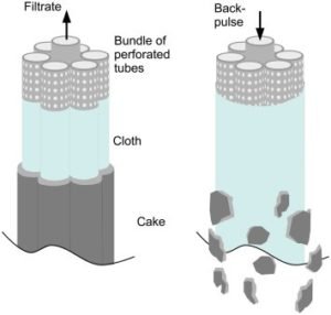
CAKE REMOVALS AND DISCHARGE
Once the filtration batch is completed (i.e. either the differential pressure is reached or the flow rate has decreased substantially) the filter has to be backwashed. For this purpose further feed to the filter shall be stopped and the outlet nozzle closed. Nitrogen / Compressed Air shall be passed in the reverse direction which will help dislodging the cake in slurry form. This backwashing of candles for cake removal shall be done in one row at a time. Removal of cake in each row will not take more than 2 minutes. The bottom cake discharge valve / quick opening type blind flange shall be opened and the cake along with the unfiltered liquid is drained from the bottom completely. To prevent gradual blinding of the filter elements a hot water backwash is to be provided again in the reverse direction keeping the bottom drain open. Now the filter is ready for next cycle of operations. Backwashing / blowback pressure shall not be less than 4 Kg/Cm²g.